LandNav - Using a map
01/03/15 13:53 Filed in: navigation
Most folks think they know how to use a map, but the actual employment is quite different than simply watching your car’s satnav and moving to another location. Check it out.
USING THE MAP
Orient the Map to North
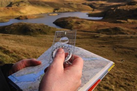
Whenever working with a map, always first orient the map to north. This allows for quick reference to where you are going and where you have been. Orienting to north makes it easier to check your location on the map using terrain association (covered below). Train yourself to do this from the beginning. Remember that west is always to your left when facing north.
To orient your map place the straight edge of your compass alongside a north/south grid line on your map. Turn the map so the north seeking arrow on the compass lines up with the 0/360 degree mark on the compass bezel.
Determining and Setting an Azimuth
The simplest way to determine your azimuth, or direction of travel, is to mark your start point, mark your desired end point, draw a straight line between the two and lay your protractor on top. The point in the center of your protractor should be on your start point. The protractor should line up squarely with the grid lines on your map: north, south, east, and west. Reading from your start point to your ending point across the protractor scale, you will find your azimuth in degrees.
Alternatively, a piece of thread can be inserted at the center of your protractor and pulled tight across your end point and protractor scale for quick azimuth reading
Reading opposite, from end point to start point, you have your back azimuth. A back azimuth is used as a simple way to retrace your steps.
An easy way to determine your back azimuth without the use of the map is:
If your azimuth is 180 degrees or more, subtract 180.
If your azimuth is less than 180 degrees, add 180 degrees.
Example: Your azimuth is 35 degrees.
35 degrees
+180 degrees
215 degrees- Your back azimuth is 215 degrees.
An Alternate Method
If necessary, you can determine your azimuth without the use of a protractor as well. With the map oriented north, lay the straight edge of the compass along the line you have drawn in your direction of travel. Rotate the bezel of the compass so that its north arrow lines up with the north seeking arrow of the compass. The reading on your compass is your map azimuth. This is an expedient method. Using a protractor is more accurate and is recommended.
There is an important point to note about compasses with a built in declination setting: if you use the alternate protractor method, you must calculate for declination. This is because you are still working from the map to the ground.
Declination
Declination is defined as the angular difference between true north and either grid (map) north or magnetic (ground) north, whichever you are working with. It is caused by the curvature of the Earth and changes from location to location. We will only be concerned with grid north, which refers to the map, and to magnetic north, which refers to the ground.
Once you have a map azimuth plotted the next step is to convert it to a ground azimuth. This is the azimuth you will dial on the bezel of your compass and use for actual navigation. If you used the alternate method and set your azimuth on the compass already, you will only need to turn the bezel the number of degrees indicated to allow for declination.
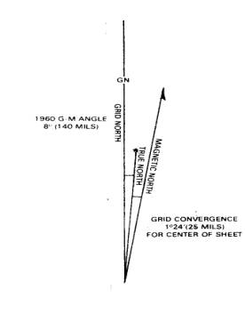
When making these conversions of azimuths you first must consult the declination diagram on your map. The declination diagram tells the amount of degrees to either add or subtract, depending on your location on the Earth, to the azimuth you are working with to convert it for use. The declination diagram on your map will tell you whether the declination is East or West and the number of degrees of declination. Figure 2 shows a declination diagram with 8 degrees east declination.
There is a basic rule to remember when converting azimuths. When working from map to ground:
If you have declination to the west, turn the dial to the west, or add.
If you have declination to the east, turn the dial to the east, or subtract.
An easy way to remember this rule is to use the acronym LARS- left add, right subtract- when working from map to ground.
Example: We have plotted an azimuth of 310 degrees on the map. Keeping in mind the basic rule, according to the declination diagram in Figure 2 we need to subtract 8 degrees, or turn the bezel 8 degrees to the east. We now have our ground azimuth of 302 degrees.
Once you have determined a ground azimuth and set it on your compass, you need only to turn your body appropriately to line up the north seeking arrow with the north arrow on the bezel. The center line of your compass points in the direction of your ground azimuth.
If you are working from the ground to the map, simply reverse the procedure.
If you keep in mind the basic rules, with practice, plotting azimuths and figuring conversions will become a simple process.
Resection
Resection is a method for obtaining your unknown position on the map using two, or preferably three, distant, well-defined features that are on your map. The process is as follows:
1) Orient your map to north.
2) Identify two or three distant locations and mark them on your map.
3) Measure the magnetic azimuth to each location from your position.
4) Convert the magnetic azimuths to grid azimuths.
5) Convert the grid azimuths to back azimuths.
6) With a protractor, draw each back azimuth from the known points to your unknown position. The intersection of the lines is your position.
Intersection
Intersection is a method for obtaining the location of an unknown, distant point on the ground through the occupation of two, or preferably three, positions on the ground.
The process is as follows:
Grid Coordinates
Grid coordinates are expressed as a name or series of letters, and a series of numbers representing your position on the map and are used for determining and communicating your location. Grid coordinates can be used to indicate your position, in theory, down to the nearest meter with some accuracy. With military or USGS maps and a plastic protractor, the most accurate you will get is an eight digit grid coordinate, down to the nearest 10 meters. Although not really necessary for hiking and backpacking, unless you are communicating your position to someone else who intends to join you, knowing how to determine grid coordinates can be extremely important in an emergency situation.
A standard convention for determining your grid coordinates, your location on a map, is the Universal Transverse Mercator grid, or UTM. A second convention, based on UTM, is the Military Grid Reference System, or MGRS. Both of these conventions use the same “grid” transposed over the Transverse Mercator Projection, a projection being a method of flattening the curved earth in order to make it usable as a map. The process of determining your coordinates is the same using either convention, with only the prefix being different. Using either convention, grid coordinates are easy to calculate provided you prepare your map and follow the simple process.
First, you must have a map that has grid squares on it. Many newer USGS maps have grid lines on them. If your map does not have grid lines they must be drawn in. Use the blue tick marks on the right and left sides and on the top and bottom. The distance between any two tick marks, or straight across a grid square, north-south or east-west is one kilometer. Line up a straight edge on the marks and draw them in with a sharp pencil. Pencil does not run as ink does if it becomes wet. Use the numbered latitude and longitude line marks along the map edges to aid in lining up the correct tick marks.
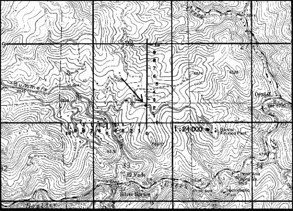
A grid coordinate scale, like the one on the military protractor, Figure 1- (a) is needed. Place the horizontal line of your scale over the east-west grid line just below your point. Place the vertical line of you scale over the north-south grid line to the west of your point. Now slide your scale, staying on the east-west line, to the east until the corner of the scale is over the point you wish to calculate for, see Figure 3. Be sure the scale sits squarely over the grid lines.
Reading right and then up, calculate your position. Using the MGRS, the full 10 digit grid coordinates in Figure 3 is 7069029210. The coordinates 7020 come directly from the grid lines on the map, found along the margin, bringing you into the 1000 meter grid square. The coordinate scale brings you down to the 10 meter level of accuracy giving you the eight digit grid coordinates 70692921. The same location stated at the 1 meter level of accuracy, or as 10 digit grid coordinates, reads 7069029210. Arriving at this level of accuracy is really not possible using a grid coordinate scale. But adding the extra zeros may be necessary at times, such as when putting the coordinates into a GPS.
The MGRS, an abbreviated version of the UTM, uses only the principle digits identifying the grid lines (found along the margin). Note that it does not use the first number reading right, nor the first two numbers reading up. Instead, military maps include in the marginal data a grid zone designator which states the location of the map sheet without using these numbers or an actual name. An example of a grid zone designator is 16SGL. These five characters, arrived at using the UTM grid, the Universal Polar Stereographic Grid (or UPS grid) and the 100,000-Meter Square, take the place of the map sheet name and the 3 eliminated numbers from the margin on USGS maps.
Full UTM coordinates for the same location calculated above would read 4706900 44292100. A full UTM coordinate has 15 numbers, 7 in the first grouping, or the Easting (reading right) and 8 in the second grouping, or Northing (reading up). Note that all three Easting digit and all 4 Northing digits from the grid lines are included with UTM coordinates.
When communicating a UTM coordinate you would need to give the full map sheet name along with the grid coordinates you have calculated. For example, in Figure 3 the map sheet is Boulder Quadrangle, Boulder, Colorado, to be followed by the 15 digit coordinates.
Finally, note how the grid coordinates using each method relate to each other:
MGRS 10 digit grid coordinates: 7069029210
Full UTM coordinates: 4706900 44292100
Section of map sheet with grid lines drawn in
Orient the Map to North
Whenever working with a map, always first orient the map to north. This allows for quick reference to where you are going and where you have been. Orienting to north makes it easier to check your location on the map using terrain association (covered below). Train yourself to do this from the beginning. Remember that west is always to your left when facing north.
To orient your map place the straight edge of your compass alongside a north/south grid line on your map. Turn the map so the north seeking arrow on the compass lines up with the 0/360 degree mark on the compass bezel.
Determining and Setting an Azimuth
The simplest way to determine your azimuth, or direction of travel, is to mark your start point, mark your desired end point, draw a straight line between the two and lay your protractor on top. The point in the center of your protractor should be on your start point. The protractor should line up squarely with the grid lines on your map: north, south, east, and west. Reading from your start point to your ending point across the protractor scale, you will find your azimuth in degrees.
Alternatively, a piece of thread can be inserted at the center of your protractor and pulled tight across your end point and protractor scale for quick azimuth reading
Reading opposite, from end point to start point, you have your back azimuth. A back azimuth is used as a simple way to retrace your steps.
An easy way to determine your back azimuth without the use of the map is:
If your azimuth is 180 degrees or more, subtract 180.
If your azimuth is less than 180 degrees, add 180 degrees.
Example: Your azimuth is 35 degrees.
35 degrees
+180 degrees
215 degrees- Your back azimuth is 215 degrees.
An Alternate Method
If necessary, you can determine your azimuth without the use of a protractor as well. With the map oriented north, lay the straight edge of the compass along the line you have drawn in your direction of travel. Rotate the bezel of the compass so that its north arrow lines up with the north seeking arrow of the compass. The reading on your compass is your map azimuth. This is an expedient method. Using a protractor is more accurate and is recommended.
There is an important point to note about compasses with a built in declination setting: if you use the alternate protractor method, you must calculate for declination. This is because you are still working from the map to the ground.
Declination
Declination is defined as the angular difference between true north and either grid (map) north or magnetic (ground) north, whichever you are working with. It is caused by the curvature of the Earth and changes from location to location. We will only be concerned with grid north, which refers to the map, and to magnetic north, which refers to the ground.
Once you have a map azimuth plotted the next step is to convert it to a ground azimuth. This is the azimuth you will dial on the bezel of your compass and use for actual navigation. If you used the alternate method and set your azimuth on the compass already, you will only need to turn the bezel the number of degrees indicated to allow for declination.
When making these conversions of azimuths you first must consult the declination diagram on your map. The declination diagram tells the amount of degrees to either add or subtract, depending on your location on the Earth, to the azimuth you are working with to convert it for use. The declination diagram on your map will tell you whether the declination is East or West and the number of degrees of declination. Figure 2 shows a declination diagram with 8 degrees east declination.
There is a basic rule to remember when converting azimuths. When working from map to ground:
If you have declination to the west, turn the dial to the west, or add.
If you have declination to the east, turn the dial to the east, or subtract.
An easy way to remember this rule is to use the acronym LARS- left add, right subtract- when working from map to ground.
Example: We have plotted an azimuth of 310 degrees on the map. Keeping in mind the basic rule, according to the declination diagram in Figure 2 we need to subtract 8 degrees, or turn the bezel 8 degrees to the east. We now have our ground azimuth of 302 degrees.
Once you have determined a ground azimuth and set it on your compass, you need only to turn your body appropriately to line up the north seeking arrow with the north arrow on the bezel. The center line of your compass points in the direction of your ground azimuth.
If you are working from the ground to the map, simply reverse the procedure.
If you keep in mind the basic rules, with practice, plotting azimuths and figuring conversions will become a simple process.
Resection
Resection is a method for obtaining your unknown position on the map using two, or preferably three, distant, well-defined features that are on your map. The process is as follows:
1) Orient your map to north.
2) Identify two or three distant locations and mark them on your map.
3) Measure the magnetic azimuth to each location from your position.
4) Convert the magnetic azimuths to grid azimuths.
5) Convert the grid azimuths to back azimuths.
6) With a protractor, draw each back azimuth from the known points to your unknown position. The intersection of the lines is your position.
Intersection
Intersection is a method for obtaining the location of an unknown, distant point on the ground through the occupation of two, or preferably three, positions on the ground.
The process is as follows:
- Orient your map to north.
- Locate and mark you position.
- Measure the magnetic azimuth to the unknown point.
- Convert the magnetic azimuth to grid azimuth.
- Draw a line on this grid azimuth from your position on the map.
- Move to a second location and repeat steps 1 through 5.
- Move to a third location and repeat steps 1 through 5, if desired.
Grid Coordinates
Grid coordinates are expressed as a name or series of letters, and a series of numbers representing your position on the map and are used for determining and communicating your location. Grid coordinates can be used to indicate your position, in theory, down to the nearest meter with some accuracy. With military or USGS maps and a plastic protractor, the most accurate you will get is an eight digit grid coordinate, down to the nearest 10 meters. Although not really necessary for hiking and backpacking, unless you are communicating your position to someone else who intends to join you, knowing how to determine grid coordinates can be extremely important in an emergency situation.
A standard convention for determining your grid coordinates, your location on a map, is the Universal Transverse Mercator grid, or UTM. A second convention, based on UTM, is the Military Grid Reference System, or MGRS. Both of these conventions use the same “grid” transposed over the Transverse Mercator Projection, a projection being a method of flattening the curved earth in order to make it usable as a map. The process of determining your coordinates is the same using either convention, with only the prefix being different. Using either convention, grid coordinates are easy to calculate provided you prepare your map and follow the simple process.
First, you must have a map that has grid squares on it. Many newer USGS maps have grid lines on them. If your map does not have grid lines they must be drawn in. Use the blue tick marks on the right and left sides and on the top and bottom. The distance between any two tick marks, or straight across a grid square, north-south or east-west is one kilometer. Line up a straight edge on the marks and draw them in with a sharp pencil. Pencil does not run as ink does if it becomes wet. Use the numbered latitude and longitude line marks along the map edges to aid in lining up the correct tick marks.
A grid coordinate scale, like the one on the military protractor, Figure 1- (a) is needed. Place the horizontal line of your scale over the east-west grid line just below your point. Place the vertical line of you scale over the north-south grid line to the west of your point. Now slide your scale, staying on the east-west line, to the east until the corner of the scale is over the point you wish to calculate for, see Figure 3. Be sure the scale sits squarely over the grid lines.
Reading right and then up, calculate your position. Using the MGRS, the full 10 digit grid coordinates in Figure 3 is 7069029210. The coordinates 7020 come directly from the grid lines on the map, found along the margin, bringing you into the 1000 meter grid square. The coordinate scale brings you down to the 10 meter level of accuracy giving you the eight digit grid coordinates 70692921. The same location stated at the 1 meter level of accuracy, or as 10 digit grid coordinates, reads 7069029210. Arriving at this level of accuracy is really not possible using a grid coordinate scale. But adding the extra zeros may be necessary at times, such as when putting the coordinates into a GPS.
The MGRS, an abbreviated version of the UTM, uses only the principle digits identifying the grid lines (found along the margin). Note that it does not use the first number reading right, nor the first two numbers reading up. Instead, military maps include in the marginal data a grid zone designator which states the location of the map sheet without using these numbers or an actual name. An example of a grid zone designator is 16SGL. These five characters, arrived at using the UTM grid, the Universal Polar Stereographic Grid (or UPS grid) and the 100,000-Meter Square, take the place of the map sheet name and the 3 eliminated numbers from the margin on USGS maps.
Full UTM coordinates for the same location calculated above would read 4706900 44292100. A full UTM coordinate has 15 numbers, 7 in the first grouping, or the Easting (reading right) and 8 in the second grouping, or Northing (reading up). Note that all three Easting digit and all 4 Northing digits from the grid lines are included with UTM coordinates.
When communicating a UTM coordinate you would need to give the full map sheet name along with the grid coordinates you have calculated. For example, in Figure 3 the map sheet is Boulder Quadrangle, Boulder, Colorado, to be followed by the 15 digit coordinates.
Finally, note how the grid coordinates using each method relate to each other:
MGRS 10 digit grid coordinates: 7069029210
Full UTM coordinates: 4706900 44292100
Section of map sheet with grid lines drawn in